

Industrial Fan Static Pressure: Why Installed Airflow Falls Short
Industrial fan static pressure is the resistance a fan must overcome to move air through a real system. Installed airflow is therefore not the largest m³/h or CFM value listed in a catalog. It is the flow at the point where the fan’s performance curve intersects the resistance curve of the ducts, louvers, filters, hoods, and other components.
For a defensible selection, define both parts of the duty point: required airflow and required pressure. A free-air rating measured near zero pressure may be useful for comparison, but it cannot predict airflow after the fan is connected to a restrictive system.
What Industrial Fan Static Pressure Actually Measures
Static pressure expresses the pressure rise needed to overcome resistance to airflow. It is commonly expressed in pascals (Pa) or inches of water gauge (in. w.g.). Airflow, by contrast, is a volume rate stated in m³/h, m³/s, or CFM. The two values describe different quantities, but they must be considered together for fan selection.
Pressure terminology also matters. Fan static pressure and fan total pressure are not interchangeable. The equipment schedule, fan curve, and test report should use the same pressure basis. Air density and test conditions should also be stated because temperature, altitude, and gas composition can affect fan performance and power requirements.
How the Operating Point Determines Real Airflow
A fan curve shows how a particular fan behaves at a stated speed and air density. Flow generally decreases as the pressure requirement rises. A system curve describes how much resistance the installed air path creates at different flow rates. Their intersection defines is the operating point the combined fan and system will tend to reach.
For a fixed duct system in predominantly turbulent flow, the relationship is often approximated as:
ΔP = KQ²
Here, ΔP is system pressure loss in Pa, Q is airflow in one consistent unit such as m³/s, and K is a system-resistance coefficient for that flow unit. This is an approximation for a fixed geometry and air density. A change in damper position, filter loading, or duct routing changes the system resistance and therefore the operating point.
DAIHO Ventilation’s roof exhaust fan sizing guide applies this same principle to curbs, dampers, screens, and air-inlet availability.
Why Free-Air Ratings Fail in Real Installations
Free-air operation means the fan operates with little external resistance. An installed system is rarely that simple. Inlet guards, shutters, roof caps, transitions, bends, long ducts, coils, filters, silencers, and discharge fittings each add pressure loss. Inadequate make-up-air openings can add another restriction on the building side.
These effects cannot be accounted for by simply subtracting an arbitrary percentage from the catalog airflow. The reduction depends on the shape of the specific fan curve and the combined system curve. Two fans with the same free-air rating can deliver very different flow at 300 or 500 Pa.
A Worked Fan Curve Example
Assume an engineer has calculated a design requirement of 10,000 m³/h at 450 Pa. A candidate fan is advertised at 12,400 m³/h in free air, but its curve shows only 8,100 m³/h at 450 Pa.
| Value | What It Represents | Selection Meaning |
| 12,400 m³/h at 0 Pa | Candidate’s illustrative free-air point | Not the project duty |
| 8,100 m³/h at 450 Pa | Candidate’s illustrative curve point | Below the required airflow |
| 10,000 m³/h at 450 Pa | Illustrative project duty point | Target duty point |
The candidate is not supported for the stated duty, despite its larger headline airflow. The next step is to identify a model whose tested curve includes the required point, then verify motor load, efficiency, sound, and stable operation near that point. These numbers are illustrative and do not represent a specific DAIHO Ventilation model.
Where System Resistance Comes From
Pressure loss begins before air reaches the fan and continues after it leaves. Poor inlet clearance, sharp transitions, flexible duct, tight elbows, undersized ductwork, partially closed dampers, and restrictive discharge terminals can all shift the operating point. The pressure loss of a dirty filter may be much greater than its clean initial resistance.
System effects deserve separate attention. A fan tested with a uniform inlet may perform differently when installed immediately after an elbow or beside an obstruction. Likewise, an exhaust fan cannot deliver its intended flow if replacement air has no adequate path into the building. Calculate resistance for the actual layout and for relevant operating states, not only the cleanest condition.
How Fan Type Influences Pressure Capability
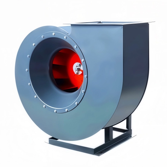
Fan type narrows the field but does not replace curve verification. DAIHO Ventilation axial flow fans are relevant to high-volume applications where the air path has relatively low resistance. DAIHO Ventilation’s centrifugal fans are suited to industrial ventilation systems where higher pressure capability is required.
As a general pattern, axial fans suit wall openings, roof exhaust, and short uncomplicated paths. Centrifugal fans are more often considered for longer duct runs, filters, hoods, or systems with multiple fittings. DAIHO Ventilation’s axial and centrifugal fan comparison explains these application differences. The final decision should still be based on the proposed model’s performance curve at the required speed and density.
The Data That Makes a Selection Verifiable
A verifiable selection identifies the design airflow; static or total pressure; air temperature, density, and contaminants; clean and loaded filter losses; fan speed; motor input and allowable load; efficiency; sound data; and any unstable operating region. Variable-speed applications also require performance curves or validated data across the proposed control range.
Keep units and pressure definitions consistent. A single maximum-airflow figure, a maximum-pressure figure taken from another operating point, and a motor rating do not combine into a valid duty point.
FAQ
The following questions clarify common points that arise when buyers compare industrial fan data.
Is Static Pressure the Same As Airflow?
No. Static pressure describes resistance or pressure capability, while airflow describes the volume moved per unit of time. The fan curve connects them at a particular speed and air density.
Does a Higher Static Pressure Rating Mean a Better Fan?
Not by itself. A suitable fan must provide the required airflow at that pressure while remaining within acceptable efficiency, motor load, sound, and operating-stability limits.
Why Does Adding a Filter Reduce Airflow?
A filter adds resistance, shifting the system curve toward a higher pressure requirement. Unless fan speed or capability compensates, the new curve intersection occurs at a lower airflow.
Can I Calculate Installed Airflow Without a Fan Curve?
Not reliably. A pressure-loss calculation describes the system, but the fan curve is needed to show how the proposed fan responds to that resistance.
Which Fan Type Handles Higher Static Pressure?
Centrifugal designs commonly serve higher-resistance systems, while axial designs commonly serve high-volume, lower-resistance paths. Always confirm the proposed model at the complete duty point.
Turn the Duty Point into a Model Decision
Before comparing models, assemble the required airflow, calculated pressure, pressure basis, air conditions, system layout, filter states, electrical supply, and control method. You can contact DAIHO Ventilation for a model review using those project inputs. Final system design and compliance should be confirmed by a qualified ventilation professional.
 English
  Russian
  Arabic
  Spanish
  French
  Italian